
The Evolution of Diaphragm Metering Pumps: A Technical History
If you’ve ever injected a chemical into a process stream with extremely tight dosing limits (often under 1% accuracy), you’ve depended on a long history of incremental engineering improvements. The story of diaphragm metering pumps shows how a relatively simple mechanical concept can evolve into a high-precision dosing tool.
Early Days: Tackling Leakage Before Precision Was the Goal
Membrane-style pumps existed well before they were used for precise metering. In the early 1900s, flexible-membrane pumps were mainly applied to challenging fluids like abrasive slurries and corrosive chemicals—situations where piston-based sealing could quickly wear out or fail.
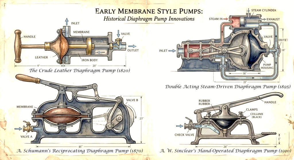
The key idea was straightforward: instead of using a piston that directly slides and seals against a cylinder (which tends to leak as seals degrade), the pump uses a flexible diaphragm that moves back and forth. This diaphragm physically separates the process fluid from the mechanical drive components. As a result, the driving mechanism can keep running without being directly exposed to the process liquid.
At this stage, “metering” (accurate, adjustable, repeatable dosing) wasn’t the primary focus. The bigger value was reliable transfer of difficult fluids with reduced leakage risk.
Mechanically Actuated Metering Pumps
Once industries started demanding controlled chemical dosing, especially from chemical processing and water treatment sectors around the mid-20th century, true metering pump designs began to take shape.
The earliest metering pumps used a mechanically driven diaphragm. A rod or connecting link, powered by a cam or crank, flexed the diaphragm each stroke. This approach was rugged and easy to build, and it’s still used in many applications today. However, it came with a major drawback: the diaphragm endured concentrated mechanical stress with every cycle. That made fatigue and rupture more likely over time. If the diaphragm failed, process fluid could potentially move back toward the mechanical drive area.
Manufacturers responded over time by improving diaphragm materials. The industry moved from early rubber-based options to PTFE (polytetrafluoroethylene, commonly known as Teflon). PTFE became dominant because it provides strong chemical resistance and better fatigue performance across a wide range of aggressive reagents.
The Big Shift: Hydraulic Actuation
A major design breakthrough arrived with hydraulically actuated (often “hydraulically balanced”) diaphragm pumps, which gained wider adoption from the 1960s onward.
In this configuration, the diaphragm isn’t pushed directly by a rod. Instead, a piston applies force to hydraulic oil that sits behind the diaphragm. The hydraulic pressure flexes the diaphragm through its stroke.
This architecture improved performance in several important ways:
- Longer diaphragm life: stress is distributed more uniformly rather than being concentrated at a single contact point.
- Higher pressure capability: the hydraulic oil system bears much of the mechanical loading that would otherwise stress the diaphragm directly.
- Better safety features: it became practical to use multi-layer diaphragms, including leak-detection designs (such as a monitored cavity between PTFE layers). If the process-side layer fails, detection can occur before hydraulic oil—or process fluid—escapes containment.
For pumps handling dangerous or high-value chemicals, this multi-layer, leak-aware approach became a major reliability and safety advantage.
Improving Accuracy: Control Systems Evolve
Early metering pumps were adjusted mechanically. This was often done by changing stroke length with dials and performing adjustments while operating. While that could offer reasonable “turn-down” (range of dosing rates), it limited how quickly the pump could respond to changing conditions.
As electronics and variable drives advanced, pumps added features like variable-speed actuation. Over time, manufacturers moved toward digital control of stroke length and stroke rate, enabling near-real-time response to process signals (for example, signals from flow instruments). This made automated dosing far more practical and repeatable.
The hydraulic system also became more sophisticated. Enhancements such as automatic degassing helped remove air that could affect hydraulic performance and responsiveness. Pressure relief and bypass protection added additional safeguards. And as leak-detection sensors and monitoring became integrated, diaphragm metering pumps shifted from being purely mechanical devices to more instrumented, system-level components.
The State of Modern Diaphragm Metering Pumps
Today’s diaphragm metering pumps typically combine:
- multi-layer PTFE diaphragms
- hydraulic balancing
- digital control electronics
In many cases, modern systems achieve dosing accuracy and repeatability near ±1% of the setpoint. This is something early mid-century designers could hardly have imagined. Many “smart” pumps can connect directly to plant control systems, monitor diaphragm condition, and adjust output based on real-time feedback rather than relying only on manual dial settings. While digital controls add some features and flexibility, there are some manufacturers who continue to manufacture simple rugged pumps that have manual adjustments. These companies often have long-standing relationships with clients who are used to their pumps, continue to reorder, and would rather things stay the same.
The Common Thread
Despite all the technological progress, the core principle hasn’t changed: a flexed membrane isolates the process fluid from the mechanical actuation. Most advances—better materials, safer multi-layer designs, improved hydraulic actuation, and more precise digital controls—are refinements to that same fundamental concept, aimed at increasing precision while reducing risk.